

Blogs
Methods to Prevent Butterfly Valve Leakage
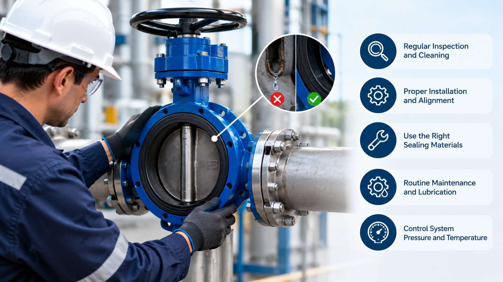
A butterfly valve that leaks is usually pointing at something around it: the seat material, the flange, the actuator stop, or the fluid itself. As a China-based butterfly valve manufacturer, Kunjian Tech looks at leakage from the design and sealing side as well as the installation side, because the two are tightly linked. This guide covers the three places a butterfly valve can leak, what causes each, and how to prevent them through selection, installation, operation and maintenance.
Quick answer: Match the seat and valve design to the real fluid, temperature and differential pressure. Flush and align the line before installing. Set the actuator's closed stop with the valve in the pipe. Keep throttling and cycling within the manufacturer's limits. Replace seats and stem seals on condition, not on failure. Test any repair against a defined leakage standard.
Start With the Leak Path
Most troubleshooting advice treats "leakage" as one problem. It is three, and each has a different fix.
| Leak path | What you see | Usual causes | Where to look |
|---|---|---|---|
| Through the seat (internal) | Flow or pressure rise downstream with the valve closed | Debris on the seat, worn or hardened seat, damaged disc edge, wrong closed-position stop, seat attacked by the fluid, differential pressure above rating | Sections 1, 2, 3 and 5 |
| Stem or shaft (external) | Weeping at the stem neck or actuator mounting | Worn packing or stem seals, loose gland, scored stem, worn bearings, side load from a misaligned actuator | Section 4 |
| Body, flange or liner edge (external) | Seepage at the flange face or between liner and body | Warped or misaligned flanges, wrong gasket arrangement, uneven bolting, displaced liner | Section 2 |
Identify the path first. Re-tightening a gland will not stop seat leakage, and replacing a seat will not fix a leaking stem.
1. Prevent Leakage at Selection: Match the Valve to the Duty
Many leaks are specified into the pipeline. The valve works as designed, but the design does not suit the service.
Choose the Right Design for the Duty
- Concentric (centreline) valves: Use a resilient liner or seat. The disc rubs against the seat through most of its stroke, so seat wear depends on cycle count and differential pressure. They suit water, HVAC and general utility duty.
- Double-offset valves: Move the shaft away from the seat centreline. The disc lifts off the seat early in opening, which reduces rubbing and extends seat life in demanding duty.
- Triple-offset valves: Add a conical seat geometry so the disc seats with a cam-like action. They normally use metal seats and are closed against a controlled torque, which makes them the usual choice for high temperature or severe service.
Do not expect a rubber-seated concentric valve to perform where it is a poor fit: high temperature, steam, abrasive slurry, or sustained throttling. For a general comparison with other isolation valves, see our guide to butterfly valve vs gate valve.
Match the Seat to the Whole Fluid, Not Just the Main Medium
Seat compounds fail by swelling, hardening or chemical attack. The usual cause is something in the line that the datasheet never listed, such as cleaning chemicals, lubricants carried over from pumps, or oil in compressed-air condensate.
| Seat material | Typically suits | Be careful with | Typical catalogue temperature range* |
|---|---|---|---|
| EPDM | Water, many acids and alkalis, many ketones and alcohols | Mineral oils, fuels, hydrocarbon solvents (EPDM swells) | About −30 to 120 °C |
| NBR (nitrile) | Oils, fuels, aliphatic hydrocarbons | Ketones, strong oxidisers, aromatic and chlorinated solvents, ozone | About −30 to 100 °C |
| FKM (Viton) | Fuels, oils, aromatics, many acids, higher temperatures | Amines, ketones, low-molecular-weight esters; not a default choice for hot water or steam | About −20 to 200 °C |
| PTFE (including PTFE-lined elastomer) | Broad chemical resistance | Stiff material with limited elasticity: it creeps under load, is more sensitive to debris and disc-edge damage, and usually needs more torque | Varies with design and pressure; confirm on the datasheet |
*Ranges vary by compound, pressure and valve design. Treat them as a screening guide and confirm limits against the manufacturer's pressure-temperature data. Kunjian's soft seal butterfly valve is offered with EPDM, NBR, Viton and PTFE seat options, so seat selection can be matched to the application.
Check the Conditions Most Buyers Leave Off the Enquiry
- Differential pressure when closed: Butterfly valves are normally rated by maximum differential pressure. Give the real figure, including surge, not just line pressure.
- Seating direction: Concentric valves are commonly bidirectional. Many double-offset and triple-offset valves have a preferred seating direction marked on the body. Check the valve before assuming either.
- Vacuum service: Some liner designs can collapse or lift under vacuum. Confirm the valve's vacuum rating.
- Dead-end service: Isolating a line with one flange removed is not allowed on every valve. Some wafer valves are not rated for it, and lugged valves may be rated only at reduced pressure with a blind flange fitted. Confirm with the manufacturer.
Specify Leakage Properly
"Bubble-tight" is not a specification. State the test standard and the leakage rate, for example API 598 or ISO 5208 / EN 12266-1.
Resilient-seated butterfly valves are typically specified to no visible leakage (ISO 5208 Rate A) during the test. Metal-seated valves are usually specified to a defined, small allowable rate, so they should not be expected to be bubble-tight unless the order says so. Also state the test direction and differential pressure. Ask the supplier for the test report and acceptance criteria.
2. Install Correctly: Where Many Seat and Flange Leaks Begin
Installation faults are often invisible until the line is pressurised. These steps prevent the most common ones.
- Store the valve properly. Keep it packed and clean until installation so dust does not settle on the seat. Many manufacturers recommend storing resilient-seated valves with the disc slightly open to avoid permanent set.
- Prepare the line. Flush the pipe and remove weld slag, rust and construction debris. Never weld flanges with the valve in place, because heat can damage the seat.
- Check the flange bore against disc swing. Heavy-wall pipe, rubber-lined pipe and HDPE stub ends can reduce the bore enough for the open disc to strike the pipe. Open the disc slightly and check clearance before final tightening.
- Follow the manufacturer's gasket instructions. On many resilient-seated wafer and lug valves, the seat liner also seals the flange face, so an extra gasket may intrude into the bore and interfere with the disc. Flanged-end valves normally need gaskets. Check which applies.
- Fit the valve with the disc slightly open. This prevents the disc edge and seat from being pinched or damaged as the flanges close.
- Tighten bolts evenly in a cross pattern. Over-tightening squeezes liner material into the bore, which can raise torque and distort the sealing surface.
- Keep pipe strain out of the valve. Support the pipe and align flanges before bolting. Do not use the valve body to pull misaligned flanges together.
- Observe flow direction on directional valves. Fitting an offset or triple-offset valve against its marked seating direction can cause immediate seat leakage or reduce its pressure capability.
- Think about stem orientation in dirty service. In lines that carry solids, a horizontal stem is often preferred so sediment does not collect around the lower bearing and stem seal. Follow the manufacturer's instruction for the valve size.
- Commission before service. Cycle the valve slowly, check for disc-to-pipe contact, then pressure test the piping. Do not hydrotest across a closed valve above its rated differential pressure. That alone can show up as seat leakage.
For double-flange installations, Kunjian's flanged butterfly valve is a concentric design that suits large-diameter piping.
3. Set Up the Actuator and Operate the Valve Within Its Limits
Set the Closed Position Carefully
Seat leakage often traces back to the closed stop.
- Under-travel: Leaves a small gap at the disc edge, so the valve passes flow.
- Over-travel: Crushes the elastomer or damages the disc edge, and the leak shows up later.
Set the stop with the valve installed in the pipe and no differential pressure. On many designs the actuator's travel stop should carry the closing torque, not the stop inside the valve body. Confirm this with the actuator and valve manuals.
How the valve seats also matters:
- Resilient concentric valves: Seat by interference. They are position-seated, so the limit switch should stop the actuator and the torque switch should act as a back-up.
- Metal-seated offset valves: Are typically torque-seated. Closing torque controls the seat load. Check it against the manufacturer's figure.
Check shaft couplings too. Loose couplings add lost motion, so the disc may not reach the closed position even though the actuator indicator says it has.
Avoid Duty That Wears the Seat
- Throttling: Low openings under high differential pressure are where cavitation, erosion of the disc edge and seat damage begin. Use the manufacturer's flow coefficient and cavitation data before using an isolation valve to regulate flow.
- Fast closure: A quarter-turn valve can close quickly enough to cause a pressure surge in liquid lines. Fit speed control on the actuator where transient pressure is a concern.
- Abrasive media: Solids wear the seat edge and the disc. Standard resilient-seated valves are not designed for heavy slurry.
- Valves that rarely move: Seats take a set and can stick. Exercise infrequently operated valves on a schedule so the first movement does not tear the seat.
- Temperature and pressure beyond the rating: Elastomers harden and crack above their limit. Differential pressure above the rating deforms the seat and opens a leak path.
4. Stop Stem and Shaft Leaks
The fix depends on how the valve is sealed at the stem.
- Packing or gland arrangements: Tighten the gland evenly in small steps. If you repeatedly tighten the gland to stop a leak, the packing is worn or the stem is damaged. Replace it instead. Over-tightening adds friction and raises operating torque.
- O-ring and cartridge seals: These are not adjustable. Replace the seal if it weeps.
Common root causes:
- Debris or corrosion scoring the stem.
- Worn bearings letting the stem side-load the seal.
- Actuator misalignment applying a bending load to the stem.
- Vibration or pressure cycling loosening the gland.
- A stem material unsuitable for the environment, such as stainless steel stems needed for corrosive or wastewater service.
5. Preventive Maintenance: Inspect on Condition
The table below is a practical starting point. Shorten the intervals for severe, abrasive, hot or frequently cycled service, and follow the manufacturer's manual.
| Interval | Task | What it prevents |
|---|---|---|
| About every 6 months | Check the stem and gland for weeping, flange bolts, actuator mounting and coupling. Cycle the valve and note the operating torque. | External leaks and early seat problems |
| Annually | Close the valve and check for leakage. Verify the closed stop and limit-switch settings. | Gradual seat leakage and stop drift |
| Planned shutdown, or every 2–3 years in severe duty | Remove the valve. Inspect the seat, disc edge, stem and bearings. | Wear that is invisible in service |
Maintenance practices that make the biggest difference:
- Treat torque as a diagnostic. Rising operating torque often signals seat swelling, deposits or a dry stem. A sudden drop with new leakage often means a worn seat.
- Replace seats on condition. Replace for hardening, cracking, swelling, permanent flattening, or nicks across the sealing band. Inspect the disc edge at the same time. A new seat will still leak against a scored disc.
- Use compatible lubricants. Petroleum-based grease can swell EPDM. Use the lubricant the manufacturer specifies.
- Log leakage and torque. Trends show a failing seat before it becomes an outage.
- Keep seat kits for critical valves. Some soft-seated designs allow the seat to be replaced without cutting the valve out of the line, as described for Kunjian's soft seal range. Confirm this for your size and body style.
6. Troubleshooting a Valve That Already Leaks
Before any work, isolate the line, depressurise and drain it, and lock out the actuator. Spring-return actuators can store energy, and the media may be hazardous.
| Symptom | Likely cause | What to check | Fix |
|---|---|---|---|
| Leaks from first use after installation | Debris, closed stop out of position, flange misalignment | Inspect the seat from the downstream side with the line empty. Check stop setting. | Flush by cycling the valve, reset the stop, realign the flanges. |
| Leaks only at higher pressure | Differential pressure above rating, seat deformation | Compare actual differential pressure with the valve rating. | Reduce pressure or move to a higher-rated or different design. |
| Leakage and torque rise together over time | Seat swelling or chemical attack | Compare the seat compound against the actual fluid and cleaning chemicals. | Change the seat material. |
| Leaks on one part of the seat | Disc edge damage, trapped debris, partial closure | Inspect the disc edge and the seat band. | Clean or repair the disc, replace the seat. |
| Leaks after seat replacement | Scored disc edge, wrong seat size, disc not centred on the shaft | Inspect the disc and the seat fit. | Repair or replace the disc, correct the assembly. |
| Weeping at the stem | Packing wear, damaged stem seal, scored stem | Check gland, stem surface and bearing play. | Replace packing or seal, replace the stem if scored. |
Repair or replace? Repair on site if the cause is debris, a gland, a stop setting or a replaceable seat. Replace the valve if the body seat area is damaged on a non-replaceable design, the disc edge is badly worn, or the same fault keeps returning under the same conditions. A repeat fault usually means the original specification does not fit the duty.
7. Verify the Fix
Test the valve after any repair or commissioning:
- Pressurise from the correct side, at or below the rated differential pressure.
- Hold for the time required by the chosen standard.
- Judge the result against the leakage rate that was specified, such as no visible leakage for a resilient-seated valve.
- Record the result and the date. This becomes the baseline for later inspections.
Frequently Asked Questions
Why Does My Butterfly Valve Leak When Fully Closed?
The common causes are debris on the seat, a worn or chemically damaged seat, a damaged disc edge, or a closed stop set too short or too far. Check these in that order, with the line isolated.
Can a Butterfly Valve Achieve Zero Leakage?
Resilient-seated valves can reach no visible leakage under test conditions, such as ISO 5208 Rate A. Metal-seated valves are normally specified with a small allowable leakage rate. Leakage in service depends on debris, wear, temperature and differential pressure.
How Often Should the Seat Be Replaced?
There is no fixed interval. Service life depends on cycle count, temperature, differential pressure, fluid and solids content. Replace the seat on condition, using leakage and torque trends and inspection results.
Do Wafer Butterfly Valves Need Flange Gaskets?
Often not, when the seat liner extends over the flange face and seals it. Extra gaskets can intrude into the bore and interfere with the disc. Follow the manufacturer's installation instructions.
Can I Use a Butterfly Valve for Dead-End Service?
Only if the manufacturer confirms the valve is rated for it, including any condition such as a blind flange fitted on the downstream side.
What to Send With a Butterfly Valve Enquiry
Most leakage problems can be avoided if the supplier receives the real operating conditions at the start. Include:
- Fluid, including cleaning chemicals and likely contaminants.
- Normal and maximum temperature.
- Maximum differential pressure when closed, including surge.
- Seating direction, vacuum or dead-end requirements.
- Cycling frequency and any throttling duty.
- Flange standard, pipe schedule and liner or lining details.
- Actuation type.
- Required leakage rate and test standard.
Recent Post
Leave Your Comments

Zhuhai Kunjian Technology Co.,Ltd

Have a question or need a quote? Fill out this form and our team will get back to you quickly!