


Blogs
The Essential Role of Safety Valves in Well Control
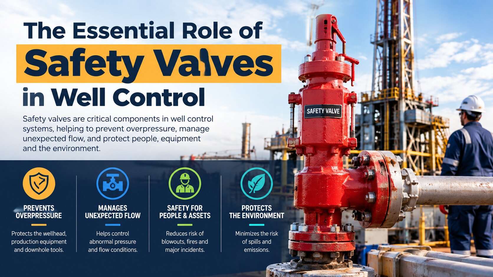
A well can move from controlled production to a serious safety event when pressure containment fails or formation fluids enter the wellbore unexpectedly. In oil and gas operations, safety valves provide critical isolation points that help control fluid movement, contain hazardous fluids, and support emergency shutdown.
However, the term safety valve covers several different types of equipment. A surface safety valve on a production tree, a subsurface safety valve inside production tubing, and a drill string safety valve serve different purposes. None should be confused with a pressure relief valve or a blowout preventer.
Understanding these differences helps drilling engineers, production teams, and procurement professionals select the right equipment, maintain well barriers, and verify that safety systems can perform when required.
What Are Safety Valves in Well Control?
Safety valves in well control are devices designed to stop or isolate fluid flow at specific points in a well or its associated production system. Depending on their design and location, they may operate manually, through a hydraulic control system, or automatically in response to defined operating conditions.
Their primary purpose is to help prevent an uncontrolled release of formation fluids, including oil, gas, and produced water.
A safety valve does not make a well safe on its own. Well control depends on multiple barriers, pressure monitoring, correctly designed equipment, competent personnel, and procedures suited to the operation.
For example, during production, a subsurface safety valve can isolate the reservoir from the upper production tubing when a shutdown condition occurs. During drilling, a drill string safety valve can provide a means of closing the drill pipe if unexpected flow enters the string.
The equipment differs, but the objective is consistent: maintain control over fluid movement and preserve the integrity of the well.
Why Safety Valves Are Essential for Well Control
Safety valves support well integrity at several stages of the well lifecycle. Their value comes from the specific barrier function they perform, not simply from their ability to open and close.
1. Preventing uncontrolled fluid flow
Formation fluids can enter a wellbore when reservoir pressure exceeds the pressure exerted by the drilling or completion fluid. This influx is known as a kick. If the influx is not recognized and controlled, it can develop into a blowout.
Safety valves provide localized isolation where their design and operating conditions allow. For example, a suitable drill string safety valve can close the drill pipe to restrict flow through the internal bore.
A critical distinction is that closing a drill string valve does not necessarily stop flow through the annulus between the drill pipe and the wellbore. Annular flow and other potential flow paths require appropriate well control equipment and procedures.
2. Supporting pressure containment
Oil and gas wells can experience high pressures, changing temperatures, corrosive fluids, and abrasive solids. Safety valves must be selected for the actual service conditions and their intended pressure containment duty.
- Their contribution to pressure control depends on several factors:
- The valve's rated working pressure and temperature limits
- The pressure differential across the closure element
- Material compatibility with the produced or injected fluids
- Seal integrity and the condition of internal components
- Correct installation and verified operating performance
A valve's pressure rating alone does not establish its suitability for every well. The complete assembly, connections, materials, operating conditions, and applicable design requirements must also be considered.
3. Enabling emergency shutdown
Surface safety valves can form part of an emergency shutdown system. Depending on the installation, the system may command a valve to close when a defined hazard or abnormal condition occurs.
Possible initiating conditions include a fire or gas detection signal, a loss of a required control condition, or an emergency shutdown command from an operator.
The intended result is to isolate the well or production flow path and reduce the release of hydrocarbons. Actual performance depends on the shutdown logic, actuator, control supply, valve condition, and system design.
4. Protecting well integrity
Well integrity means maintaining containment throughout the well's lifecycle. Safety valves contribute by providing designated barriers against unwanted flow.
A subsurface safety valve may isolate the production tubing from the reservoir, while a surface safety valve may isolate a flow path at the wellhead or production tree.
These barriers are not interchangeable. Engineers must identify the exact flow path each valve controls and determine whether additional barriers are required.
5. Reducing the consequences of equipment failure
A well control event can threaten personnel, the environment, production assets, and business continuity. Properly selected and maintained safety valves help limit the potential for uncontrolled hydrocarbon release.
Their reliability depends on more than the valve body. Control lines, hydraulic systems, actuators, seals, sensors, shutdown logic, and supporting equipment may all affect whether the required isolation occurs.
Common Types of Safety Valves Used in Well Control
The first step in choosing a valve is to identify the operation and the flow path that needs protection. The following equipment types serve distinct functions.
Surface safety valve (SSV)
A surface safety valve is installed in the surface production flow path, commonly at the wellhead or production tree. It is typically an actuated valve that can close to isolate the well from downstream production equipment.
Many production SSVs use gate valve designs with hydraulic or pneumatic actuation. The exact configuration depends on the installation.
Surface safety valves can be integrated with emergency shutdown systems so that a shutdown command closes the relevant flow path. Operators must verify both closure performance and leakage according to the applicable requirements.
An SSV does not replace a blowout preventer during drilling, and a standard industrial gate valve should not be assumed suitable for safety critical well service simply because it can shut off flow.
Subsurface safety valve (SSSV)
A subsurface safety valve is installed below the surface, commonly within the production tubing, to provide a downhole barrier.
One important type is the surface controlled subsurface safety valve (SCSSV). It is operated through a control system from the surface. In a common hydraulic design, control line pressure holds the valve open against a closing mechanism. When the required control pressure is lost, the valve is designed to close.
The closure element may use a flapper or another design, depending on the valve.
This fail safe arrangement can help isolate the well when surface control is lost. However, closure cannot be assumed under every failure condition. Mechanical damage, debris, scale, erosion, incorrect operating conditions, or a damaged sealing surface can affect performance.
SSSVs are commonly classified as tubing retrievable or wireline retrievable. A tubing retrievable valve is incorporated into the tubing assembly, while a wireline retrievable valve can be installed or retrieved through the tubing using a suitable intervention system and compatible landing arrangement.
The appropriate choice depends on well design, intervention requirements, reliability objectives, and operating conditions.
Full opening safety valve (FOSV) and TIW valve
During drilling and certain well interventions, a full opening safety valve provides a means of shutting off flow through the drill string. TIW is a commonly used name associated with this equipment category.
A full opening bore allows suitable tools and equipment to pass through when the valve is open, subject to the valve's actual dimensions and design.
The valve can be important when unexpected flow enters the drill pipe. The crew must have the correct valve, compatible connections, operating equipment, and approved procedures ready for the operation.
A full opening safety valve is not a substitute for the rig's blowout preventer system. It controls a different flow path and serves a different operational purpose.
Inside blowout preventer (inside BOP or IBOP)
An inside BOP is a drill string valve designed to restrict flow up the drill pipe under specified conditions. Certain designs act as a non return or back pressure valve, while others use a different closure arrangement.
The precise operating sequence depends on the valve design, the drill string configuration, and the well control procedure.
It is important not to treat an IBOP and a full opening safety valve as interchangeable. Their functions, internal flow restrictions, pressure ratings, and operational uses differ.
Pressure relief valve (PRV or PSV)
A pressure relief valve protects a pressure containing system from overpressure by opening at a defined pressure condition and discharging fluid through a designed relief path.
This is different from a well isolation safety valve, which generally closes to stop flow through a designated path.
Pressure relief valves can be relevant to associated oil and gas facilities, such as process vessels and piping systems. They should not be presented as direct substitutes for production SSVs, subsurface safety valves, or drilling well control equipment.
Safety Valve vs BOP: What Is the Difference?
A blowout preventer (BOP) is a major component of a drilling well control system. It can include annular and ram preventers designed to seal around tubulars, close the wellbore, or shear and seal under specified conditions when the equipment is appropriately configured.
Safety valves usually isolate particular flow paths. A drill string valve controls flow through the pipe bore, while a production safety valve isolates a designated production path.
The distinction matters because closing one valve may leave other flow paths open.
For example, if a kick enters the well during drilling, a drill string valve may help control flow inside the pipe. The BOP system addresses wellbore isolation according to the approved well control procedure. The correct response depends on the actual event, equipment configuration, and operating conditions.
Neither a safety valve nor a BOP should be assumed to provide complete protection in isolation. Effective well control relies on a properly engineered and maintained barrier system.
How Safety Valves Work During Normal Operations and Emergencies
The operating mechanism depends on the type of valve.
A manual drill string valve is operated by personnel using the specified equipment and procedure. A surface production safety valve may use an actuator controlled by a hydraulic, pneumatic, or electrical system. A hydraulically controlled subsurface safety valve typically relies on control line pressure to maintain its open position.
Consider an offshore production well with a surface controlled subsurface safety valve and a surface safety valve.
During normal production, the required control conditions keep the valves in their intended operating states. If a qualifying emergency occurs, the shutdown system can command the surface valve to close. The subsurface valve may also close when its required control pressure is removed, according to the system design.
The two valves provide isolation at different locations. This can reduce the risk of continued flow through the production path, but only if the valves and their supporting systems function correctly.
A useful engineering principle is to assess the whole system rather than a single component. Valve response time, actuator performance, control line condition, shutdown logic, leakage criteria, and independent barrier requirements all matter.
Installation Considerations for Well Control Safety Valves
Correct installation is essential to reliable valve operation. A technically suitable valve can still fail to perform if it is installed incorrectly or connected to incompatible equipment.
Before installation, engineering and operations teams should confirm the following.
Confirm the design basis
Identify the valve's intended function, location, pressure and temperature envelope, fluid composition, expected pressure differential, and required closure performance.
For sour service or other corrosive conditions, confirm the relevant material and qualification requirements rather than relying on a general description such as corrosion resistant.
Verify compatibility and connections
Confirm the connection type, dimensions, pressure rating, orientation requirements, and compatibility with the surrounding equipment. For a subsurface safety valve, the tubing configuration, landing profile, control line arrangement, and retrieval method must also be suitable.
Check control and shutdown systems
For actuated valves, verify the actuator, control supply, control lines, instrumentation, and shutdown logic as applicable. A valve that closes mechanically but cannot receive the required shutdown signal may not perform its intended safety function.
Follow approved installation procedures
Installation, pressure testing, function testing, and commissioning must follow the manufacturer's instructions and the applicable operating standards.
Drill string valve handling and operating sequences must follow the approved rig procedure. Generic instructions should not override site specific well control requirements.
Maintenance, Testing, and Inspection
A safety valve must be proven capable of performing its intended function. A closed indication alone does not establish that the valve has sealed adequately.
Maintenance programs should address the valve and its supporting equipment, including actuators, hydraulic control lines, seals, connections, instrumentation, and shutdown logic where applicable.
Functional and leakage testing
Functional testing confirms that the valve responds to the required command or operating condition. Leakage testing evaluates whether the closed valve meets the specified acceptance criteria.
The test method and allowable leakage depend on the valve type, application, governing standard, and jurisdiction.
For example, United States offshore production regulations under 30 CFR 250.880 specify that surface controlled subsurface safety valves on subsea tree wells are tested semiannually, with no more than six months between tests. The same regulation requires applicable subsea tree surface safety valves to be tested monthly, with no more than six weeks between tests. These are specific United States offshore requirements, not universal intervals for every well or every valve. Source: 30 CFR 250.880
Inspect for deterioration
Inspection should consider corrosion, erosion, seal damage, debris, scale, actuator problems, control line damage, and evidence of abnormal operation.
For valves exposed to repeated cycling or severe service, maintenance planning should account for actual operating history and manufacturer recommendations.
Document results and corrective actions
Record test dates, test methods, operating conditions, leakage results, repairs, replaced components, and return to service authorization.
If a valve fails a required test, it should be handled under the applicable corrective action and well barrier management procedures. Teams should not assume that a valve is serviceable simply because it can still be operated.
Relevant Industry Standards and Regulatory Requirements
Standards apply to different equipment categories, so the correct reference depends on the valve and its function.
API Specification 14A covers subsurface safety valve equipment and annular safety valve equipment. The American Petroleum Institute announced its 13th edition, with an Addendum 1 update listed in December 2025. Buyers should verify the current applicable edition and addenda for their project. Source: API Specification 14A
API Recommended Practice 14B addresses the design, installation, operation, testing, and redress of subsurface safety valve systems. It is particularly relevant when specifying and maintaining SCSSV systems and their associated control equipment.
API Standard 6A covers wellhead and tree equipment. Its relevance depends on the equipment being specified. It should not be treated as a blanket certification for every type of well control safety valve.
API Standard 6AV2 is referenced in United States offshore requirements for applicable surface safety valve testing. Regulatory requirements should be checked against the current rules and the specific installation.
API Recommended Practice 14C addresses safety system analysis, design, installation, and testing for offshore production facilities. It provides a broader production safety system context rather than replacing equipment specific standards.
These standards serve different purposes. Procurement teams should identify the governing specification for the exact product, verify the required edition and qualification, and request documentation appropriate to the intended service.
Regulatory requirements can differ between countries, offshore jurisdictions, and operating environments. A testing interval or certification requirement applicable to one project must not automatically be applied to another.
How to Select the Right Safety Valve for an Oil and Gas Project
For B2B buyers, selection should start with the required safety function, not the product name or advertised pressure rating.
Use the following checklist when preparing a technical inquiry.
- Define the application. Specify drilling, completion, workover, production, injection, or process facility service.
- Identify the flow path. State whether the valve must isolate the drill string, production tubing, wellhead flow path, or a process pressure system.
- Confirm pressure and temperature requirements. Provide the design conditions, expected differential pressure, and applicable operating envelope.
- Specify fluid and material requirements. Include fluid composition, corrosive components, solids exposure, and sour service requirements where applicable.
- Confirm actuation and fail position. Define manual or automated operation, control supply, shutdown interfaces, and the required safe state.
- Check applicable standards and qualifications. Identify the required API specification, regulatory requirements, product qualification, and any relevant licensing obligations.
- Request technical documentation. Obtain drawings, datasheets, pressure and functional test records, material documentation, operating limits, and maintenance instructions as appropriate.
- Evaluate lifecycle support. Consider spare parts, service availability, retrievability, inspection requirements, and the supplier's ability to support the specified application
An important procurement distinction is that a general industrial pressure relief valve is not automatically suitable for well control service. Buyers should verify that the specific product has the design, qualification, documentation, and operating capability required for the application.
Common Limitations and Failure Risks
Safety valves reduce risk, but they cannot eliminate every well control hazard.
A valve may fail to close because of mechanical damage, debris, corrosion, actuator malfunction, loss of a required control function, or deterioration of sealing surfaces. A valve may also close successfully but fail to meet its leakage acceptance criteria.
Incorrect equipment selection creates another risk. A valve with an unsuitable pressure rating, incompatible connections, inadequate material resistance, or an inappropriate operating mechanism may not provide the intended barrier.
The location of the valve also matters. A closed drill string valve does not necessarily isolate the annulus. A closed surface production valve does not automatically prove that a downhole barrier is intact.
For this reason, engineers should evaluate each valve within the complete well barrier and shutdown design. The assessment must consider alternative flow paths, required independent barriers, testing evidence, and the consequences of a single component failure.
Frequently Asked Questions
What is the main role of safety valves in well control?
Their main role is to provide controlled isolation of a designated fluid flow path, helping prevent uncontrolled hydrocarbon release and supporting well integrity during normal operations and emergencies.
What is the difference between an SSV and an SSSV?
An SSV is a surface safety valve installed in a designated surface production flow path. An SSSV is a subsurface safety valve, commonly installed in production tubing, that provides a downhole isolation barrier. They protect different locations and may work together as part of the well's safety system.
Can a safety valve prevent a blowout?
A properly selected and functioning safety valve can help control a specific flow path and reduce the risk of an uncontrolled release. It cannot guarantee blowout prevention by itself. Effective well control depends on the complete barrier system, appropriate equipment, monitoring, and correct operating procedures.
How often should well control safety valves be tested?
Testing frequency depends on the valve type, governing standard, regulatory jurisdiction, and approved operating program. For example, United States offshore rules specify particular testing intervals for certain surface and subsurface safety devices. Operators should follow the requirements applicable to their installation rather than a universal schedule.
Is a pressure relief valve the same as a well control safety valve?
No. A pressure relief valve opens to discharge fluid when specified overpressure conditions occur. A well isolation safety valve generally closes to stop flow through a designated path. They serve different protective functions and are not interchangeable.
What should buyers verify before ordering a safety valve?
Buyers should confirm the intended application, pressure and temperature envelope, materials, connections, actuation, fail position, relevant standards, product qualifications, test records, and after sales support. The supplier must be able to demonstrate suitability for the specified service.
Conclusion
The essential role of safety valves in well control is to provide reliable isolation where it is needed, helping maintain pressure containment, support emergency shutdown, and protect well integrity.
Their effectiveness depends on matching each valve to its specific function. Drill string valves, surface safety valves, subsurface safety valves, and pressure relief valves are designed for different duties. Treating them as interchangeable can leave important flow paths inadequately protected.
For drilling and production teams, the priority is a verified barrier system supported by correct installation, testing, maintenance, and documented operating procedures. For procurement professionals, the priority is to confirm the precise application, applicable standards, and product qualifications before placing an order.
Selecting the correct valve is not simply a component purchasing decision. It is part of the wider engineering process that keeps wells controlled and operations safe.
Recent Post
Leave Your Comments

Zhuhai Kunjian Technology Co.,Ltd

Have a question or need a quote? Fill out this form and our team will get back to you quickly!