


Blogs
How to Measure Ball Valve Size
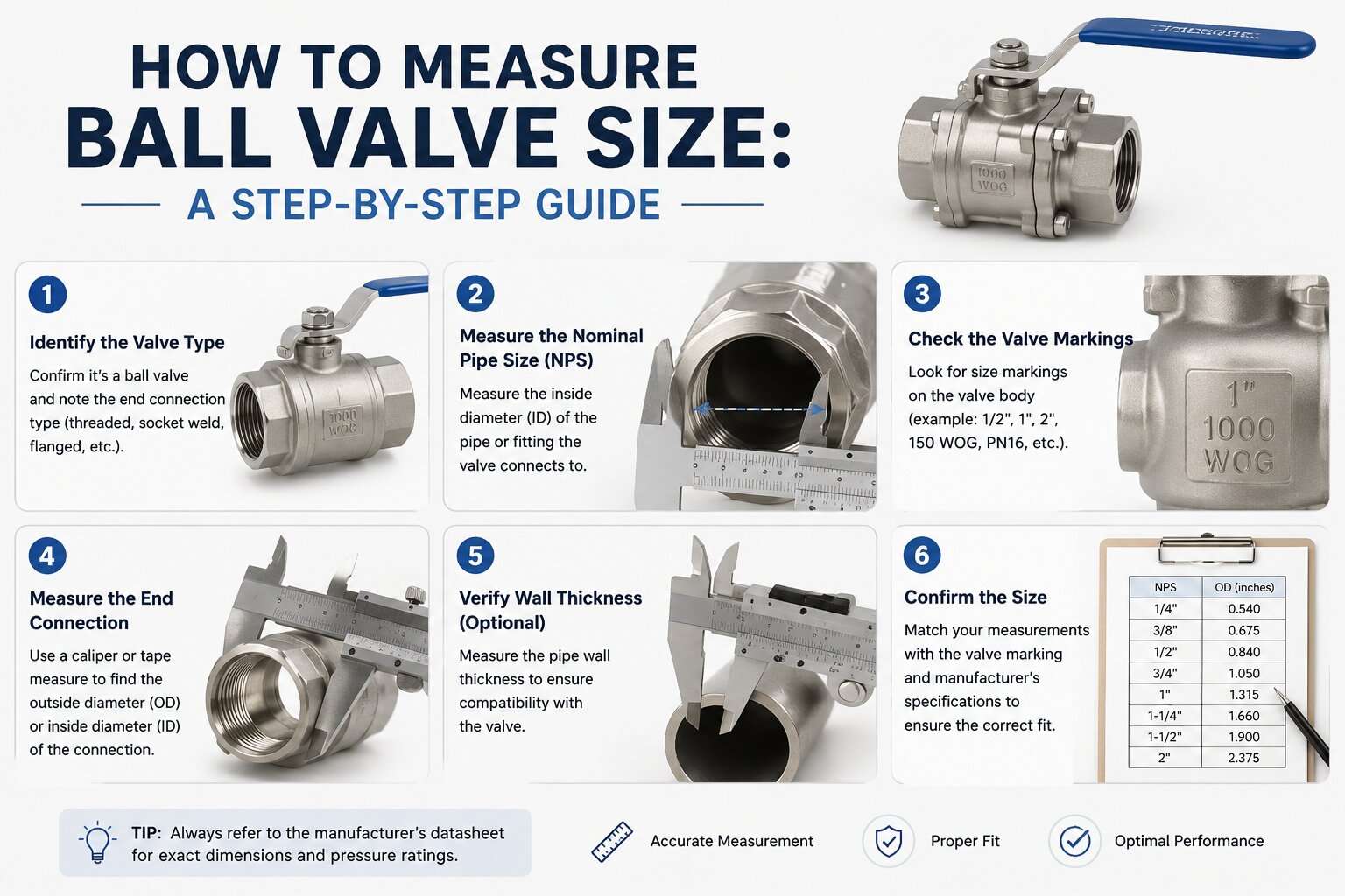
A ball valve’s size is the nominal size of its end connections. It is not the number you read when you push a caliper through the bore.
That distinction causes most wrong-size orders. A 1-inch standard-port valve has a bore of roughly 3/4 inch. A 1-inch NPT thread measures about 1.315 inches across. At 2 inches, Class 150 and PN16 flanges both have four bolt holes, yet their bolt circles differ by about 4 mm.
This guide shows you how to measure ball valve size from the valve in front of you, whether it has threaded, flanged, butt weld or socket weld ends. It then explains how to turn those measurements into a size you can order against.
Quick reference: what to measure
| End connection | Measure | It tells you |
|---|---|---|
| Threaded | Thread OD and threads per inch (TPI) | NPS and thread standard (NPT or BSP) |
| Flanged | Flange OD, bolt circle, hole count | NPS/DN and pressure class (Class or PN) |
| Butt weld | Pipe OD and wall thickness at the weld end | NPS/DN and pipe schedule |
| Socket weld | Socket bore | NPS |
| Any (valve fully open) | Bore diameter | Port type only, not valve size |
What “Ball Valve Size” Actually Means
Nominal size is a label, not a dimension
Manufacturers size ball valves by the pipe they connect to. Two systems dominate: NPS (nominal pipe size, in inches) and DN (diameter nominal, in millimetres). Both are labels. No dimension on the valve equals the label.
From 1 inch up, DN is roughly 25 times the NPS, rounded to the standard series (NPS 2 is DN50, NPS 4 is DN100). Below that, the series is irregular, so use a table. Up to NPS 12, pipe OD is larger than the NPS number. From NPS 14 up, the two are equal.
| NPS | DN | Pipe OD (in) | Pipe OD (mm) |
|---|---|---|---|
| 1/2 | 15 | 0.840 | 21.3 |
| 3/4 | 20 | 1.050 | 26.7 |
| 1 | 25 | 1.315 | 33.4 |
| 1-1/2 | 40 | 1.900 | 48.3 |
| 2 | 50 | 2.375 | 60.3 |
| 3 | 80 | 3.500 | 88.9 |
| 4 | 100 | 4.500 | 114.3 |
| 6 | 150 | 6.625 | 168.3 |
| 8 | 200 | 8.625 | 219.1 |
| 10 | 250 | 10.750 | 273.1 |
| 12 | 300 | 12.750 | 323.9 |
Why the bore is not the size
Bore tells you the port type. A full-port (full-bore) valve has a bore close to the nominal pipe size. A standard-port (reduced-bore) valve has a bore about one pipe size smaller. A 2-inch standard-port valve typically has a bore near 1-1/2 inches, yet it is still a 2-inch valve and bolts or threads onto 2-inch pipe.
Three details make bore readings even less reliable:
- “Full port” is not exactly pipe ID. MSS SP-110 sets minimum opening sizes for full-port valves. In small sizes, a valve can qualify as full port with a bore a little smaller than the inside diameter of standard-weight pipe. For 1/2-inch pipe, that ID is 0.622 in.
- Pipe ID changes with schedule. The same NPS has a different inside diameter in Schedule 40 and Schedule 80. “Matches the pipe” depends on which pipe.
- The seat can be the narrowest point. The seat ring bore can be smaller than the ball bore. Measure both and treat the smaller figure as the real flow path.
Pipeline valves add another rule. API 6D designs for pigging need a full opening, and for those lines the bore check is a hard requirement. If your project works to API 6D, the differences between API 6D and API 600 are worth reading before you spec a replacement.
Before You Measure
Isolate and depressurize the line, drain it, and apply your lockout procedure. If the valve is a trunnion-mounted double block and bleed design, vent the body cavity too, because the cavity can hold pressure after the line is isolated. Clean off scale, paint and old gasket material. A thin layer of deposit on a sealing face is enough to throw off a flange reading.
You need:
- Digital calipers (inside, outside and depth jaws)
- A steel rule or tape, long enough for the largest flange
- A thread pitch gauge, or a ruler to count threads over 1 inch
- Pi-tape or a flexible tape, if you must size the connected pipe by circumference
- A camera, for the nameplate and for a scale-in-frame photo of the flange
How to Measure Ball Valve Size, Step by Step
Step 1: Read the body markings and nameplate
Look for stamped or cast size marks (an inch value or “DN” plus a number), pressure class (150, 300, 600 or “PN16”), body material, and heat or serial numbers. Photograph all of it.
Treat markings as a lead, not proof. Valves get swapped, and a valve with a 1-inch mark on a worn body may still be a reduced-port design. You will confirm the size with the next steps.
Step 2: Identify the end connection type
Classify both ends before you measure anything. The common types are threaded (NPT or BSP), flanged (raised face, ring-type joint or flat face), butt weld, and socket weld. Some valves have different connections on each end, so check both.
Step 3: Measure the connection
Threaded ends
- For a male thread, measure the outside diameter with calipers. NPT threads taper, so measure near the base of the thread, where it is widest.
- For a female port, measure across the thread roots at the mouth, the widest points of the internal thread.
- Measure the pitch with a gauge, or count threads over 1 inch to get TPI.
- Compare both numbers to the thread table below. You need both, because OD alone does not identify a size.
| NPS | NPT OD, approx. (in / mm) | NPT TPI | BSP major dia. (mm) | BSP TPI |
|---|---|---|---|---|
| 1/2 | 0.840 / 21.3 | 14 | 20.955 | 14 |
| 3/4 | 1.050 / 26.7 | 14 | 26.441 | 14 |
| 1 | 1.315 / 33.4 | 11.5 | 33.249 | 11 |
| 1-1/4 | 1.660 / 42.2 | 11.5 | 41.910 | 11 |
| 1-1/2 | 1.900 / 48.3 | 11.5 | 47.803 | 11 |
| 2 | 2.375 / 60.3 | 11.5 | 59.614 | 11 |
Two practical points follow from this table:
- At 1 inch and above, pitch separates NPT from BSP. 11.5 TPI is NPT and 11 TPI is BSP. A pitch gauge makes the call.
- At 1/2 and 3/4 inch, the two standards look almost identical. Pitch and OD are nearly the same. The thread angle differs (60° for NPT, 55° for BSP), but you cannot judge that by eye. Confirm with a thread gauge, the mating part, or the drawing.
Also check whether the thread is tapered (NPT, BSPT) or parallel (BSPP). Parallel threads seal on a washer or O-ring, not on the thread itself.
Small floating valves are where thread identification matters most. Stainless steel floating ball valves in the DN15 to DN300 range are commonly supplied with threaded, socket weld or flanged ends, so a thread check often decides which variant you need.
Flanged ends
- Measure the flange outside diameter.
- Count the bolt holes.
- Measure the bolt circle diameter (BCD). Use opposite holes: measure from the inside edge of one hole to the outside edge of the hole directly across. Both edges sit one hole radius from their centres in the same direction, so the result equals the center-to-center distance, which is the BCD.
- Note the hole diameter and the face type (raised face, ring joint or flat).
- Compare to the flange table.
| Size | Class 150 (OD / BCD / holes) | Class 300 | PN16 |
|---|---|---|---|
| NPS 2 / DN50 | 152.4 / 120.7 / 4 | 165.1 / 127.0 / 8 | 165 / 125 / 4 |
| NPS 3 / DN80 | 190.5 / 152.4 / 4 | 209.6 / 168.3 / 8 | 200 / 160 / 8 |
| NPS 4 / DN100 | 228.6 / 190.5 / 8 | 254.0 / 200.0 / 8 | 220 / 180 / 8 |
| NPS 6 / DN150 | 279.4 / 241.3 / 8 | 317.5 / 269.9 / 12 | 285 / 240 / 8 |
All values are in mm, from ASME B16.5 and EN 1092-1. Verify against the current standard before you order.
The table shows why hole count alone fails. At NPS 4 all three patterns have 8 holes, and only the bolt circle (190.5, 200 or 180 mm) separates them. At NPS 6, Class 150 and PN16 bolt circles differ by only about 1 mm, but flange OD, bolt thread type and sealing-face details still differ. Never rely on a near match. Match the standard.
Class also tells you pressure capability. For group 1.1 carbon steel at ambient temperature, a Class 150 rating is 285 psig under ASME B16.34, and ratings fall as temperature rises. Always confirm the rating on the valve’s datasheet, not from the flange class alone.
Butt weld ends
A butt weld valve is sized by the pipe it welds to. Measure the OD at the weld end and the wall thickness, then compare the OD to the pipe table. The wall thickness sets the schedule, which determines the bevel and the bore match to the pipe. Forged steel trunnion ball valves are an example of designs offered with butt weld as well as raised face and ring joint flanged ends.
Socket weld ends
Measure the socket bore. It should be slightly larger than the OD of the pipe it accepts. Match it to the pipe OD table.
If you cannot reach the valve ends
Measure the connected pipe instead. Wrap a flexible tape around it and divide the circumference by pi. NPS 2 pipe has a circumference of about 189 mm (7.46 in). NPS 4 is about 359 mm (14.1 in). Compare the result to the pipe OD table.
Step 4: Convert your measurement to a nominal size
Match the thread OD and TPI, flange OD and bolt circle, or pipe OD to the tables above. Pick the nearest standard entry, not the nearest number. If the measured values land between two sizes, re-measure and check whether you have mixed up NPT and BSP, or Class and PN.
Step 5: Check the bore
With the valve fully open, measure the bore with inside jaws, at the narrowest point you can reach. Compare it to the nominal size:
- Bore close to nominal: full port.
- Bore about one pipe size smaller: standard (reduced) port.
For large valves, inside jaws will not reach the ball bore. Use the datasheet. Record the bore as a specification, not as the valve size.
Step 6: Measure end-to-end length and the installed envelope
Measure face-to-face (flanged) or end-to-end (threaded and weld ends) across the real sealing surfaces, with the valve off the line. Standards such as ASME B16.10 define face-to-face lengths for flanged valves. Some ball valve sizes come in both short and long patterns, so a replacement of the “same size” can still be too long or too short for the gap in the line.
Measure the envelope too: handle sweep, stem height and, for cryogenic service, the extended bonnet. Cryogenic ball valves use an extended bonnet, so their height differs from a standard valve of the same size.
Step 7: Check the stem and the actuator mounting pad
If the valve is, or will be, actuated, measure the mounting pad. ISO 5211 designates pad sizes by an F-number, set by the pad’s bolt-circle diameter:
| ISO 5211 pad | Pad bolt circle (mm) |
|---|---|
| F05 | 50 |
| F07 | 70 |
| F10 | 102 |
| F12 | 125 |
Also measure the stem drive (square size or double-D flats) and its height. A matching pad and stem are what let an actuator fit without an adapter. Trunnion designs like the two-piece trunnion mounted ball valve carry an ISO 5211 mounting pad for manual or automated operation.
Step 8: Verify against the pipe and the original specification
Cross-check the result three ways: against the markings from Step 1, against the connected pipe (circumference method), and against the original datasheet or purchase order if you have one. If two of the three disagree, stop and find out why before you order.
Common Measuring Mistakes
- Reading the bore as the size. On standard-port valves, the bore is one size smaller than the valve.
- Taking thread OD as the nominal size. A 1-inch NPT thread measures about 1.315 in. Convert with the table.
- Counting bolt holes and stopping. Hole count narrows the options. Bolt circle decides.
- Mixing standards. ASME and EN flanges, and NPT and BSP threads, can look interchangeable and are not.
- Ignoring wall thickness on weld ends. Same OD, different schedule, different bevel and bore match.
- Assuming same size means same length. Short and long patterns exist.
- Measuring over scale or a leftover gasket. A few millimetres of residue shifts a face-to-face reading.
- Skipping the stem and pad. A valve that fits the line but not the actuator is still the wrong valve.
How to Select the Correct Replacement Valve
Size is one of several specifications that must match. Use this checklist.
| Match | Why it matters | How to confirm |
|---|---|---|
| Nominal size and end connection standard | The valve must mate with the line | Steps 3 and 4 |
| Face-to-face / end-to-end length | The valve must fit the gap | Step 6 |
| Pressure class and temperature | Class sets the rating | Nameplate and datasheet |
| Port type | Affects pressure drop, pigging and velocity | Step 5 |
| Construction | Floating or trunnion, two-piece or three-piece | Original datasheet |
| Body and seat materials | Media and temperature compatibility | Original datasheet |
| Stem and mounting pad | Actuator fit | Step 7 |
| Design standard and fire-safe requirements | API 6D, API 608, ASME B16.34, API 607/6FA | Project specification |
As a rule of thumb we apply, floating designs suit lines up to about DN300 and Class 600. Larger or higher-class lines normally need trunnion mounted designs, where the ball is anchored and the seats are spring-loaded to keep operating torque down.
When you ask a supplier to quote, send the full set: size (NPS or DN), pressure class, media, minimum and maximum temperature, end connections, body and seat material, bore (full or reduced), operation (manual or automated), the applicable standard and the quantity. A photo of the nameplate and your measurements, with a ruler in frame, saves a round of questions. Our engineers can check them against the ball valve range before you commit, so send us your measurements along with your line conditions.
For wider supplier checks (documents, testing, lead times), see the B2B buyer’s guide to sourcing industrial valves.
FAQ
How do I find the size of a ball valve with no markings?
Identify the end connection, then measure it: thread OD and TPI, flange OD and bolt circle, or pipe OD at a weld end. Convert the result with the tables above. Confirm against the connected pipe.
Is ball valve size the same as pipe size?
Yes. A 2-inch valve is made for NPS 2 pipe. The valve’s bore can still be smaller than the pipe if it is a standard-port design.
Do I measure the inside or the outside of the valve?
Both, for different jobs. The outside of the connection (thread OD, flange, pipe OD) gives the size. The inside (bore) gives the port type.
How do I tell NPT from BSP?
Use a pitch gauge. At 1 inch and above, NPT is 11.5 TPI and BSP is 11 TPI. At 1/2 and 3/4 inch, both are 14 TPI, so check the thread angle with a thread gauge, the mating part or the drawing.
Is a 1/2-inch full-port ball valve’s bore really 1/2 inch?
Close, but not always exactly. MSS SP-110 allows full-port valves a bore slightly smaller than the ID of standard-weight pipe. Check the datasheet for the exact figure.
Recent Post
Leave Your Comments

Zhuhai Kunjian Technology Co.,Ltd

Have a question or need a quote? Fill out this form and our team will get back to you quickly!