


Blogs
How to Easily Install a Gate Valve
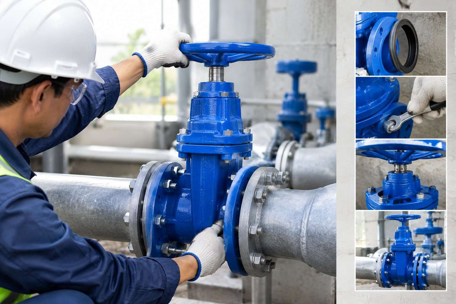
Knowing how to install a gate valve correctly takes more than bolting it between two flanges. Most early failures, such as leaking joints, stiff stems and scored seats, trace back to misalignment, debris or poor orientation rather than the valve itself. As a China-based manufacturer of API 600 cast steel gate valves, Kunjian Tech wrote this guide to cover threaded, flanged and welded connections in one sequence, and to show where the method changes.
Always follow the manufacturer’s installation, operation and maintenance (IOM) manual and your project’s piping code. Both override any general guide, including this one.
Quick Answer: The Installation Sequence
- Isolate, depressurize, drain and lock out the line.
- Inspect the valve and clean the pipeline.
- Choose the orientation: stem vertical if possible, never below the manufacturer’s limit.
- Align the connections without forcing them.
- Make the joint: sealed threads, staged flange bolting, or a procedure-controlled weld.
- Cycle the valve by handwheel, then pressure-test.
- Check the packing and joints, and record the results.
Which Installation Method Applies to Your Valve?
The connection type decides most of the work, the tools and the main risk.
| End connection | Typical use | Main risk | Core requirement |
|---|---|---|---|
| Threaded | Small-bore, lower-pressure utility lines | Thread mismatch, over-tightening that cracks the body | Matching thread standard, sealant on male threads only |
| Flanged | Most process and pipeline service | Misalignment, uneven bolt load | Parallel faces, correct gasket, staged cross-pattern tightening |
| Butt-weld (BW) | High pressure and temperature, no flange leak path | Heat damage to seats, packing and stem | Qualified weld procedure, protected internals |
| Socket-weld (SW) | Small forged valves | Cracking from no expansion gap | Set the gap before welding |
Kunjian’s cast steel gate valves are supplied with flanged (RF, RTJ) and butt-weld ends in sizes from 2" to 48", Class 150 to 2500.
Safety First: Isolate and Prepare
Most installation injuries happen before the valve is touched.
- Isolate the section, then depressurize, drain and vent it. Confirm zero pressure with a gauge, not by assumption.
- Apply lockout/tagout to every energy source, including actuators.
- Check the safety data sheet for the process media and wear matching PPE.
- Get a hot-work permit before any welding.
- Plan the lift. Large valves are heavy. Rig slings around the body, never the handwheel or stem.
- Confirm there is clear headroom for the stem and safe access to the handwheel.
Before Installation: Inspect the Valve and the Pipeline
Check the valve
- Nameplate and markings: size, pressure class, body and trim material, end type, and any flow arrow must match the datasheet and the line specification.
- Condition: remove end protectors and look into the bore for debris. Check seat faces, stem and gland bolting for transport damage or rust.
- Movement: operate the valve through full travel once by hand, then return it to the position the IOM specifies for installation. Guidance differs between designs, so do not copy what worked on a different valve.
Prepare the pipeline
- Clean it. Weld slag, scale, sand and old gasket fragments score seats and cause passing valves. Flush the line first if it is new or has had hot work.
- Check the gap. The space between flanges must equal the valve’s face-to-face dimension plus gaskets. Don’t close a short gap by stressing the valve.
- Install supports first. The valve must not carry pipe load, and heavy operators need their own support.
- Inspect the faces. Look for scratches across the sealing surface, and confirm the flange facing (RF or RTJ) matches the valve.
Orientation and Placement: Decide Before You Connect
Stem position
A vertical stem with the handwheel on top is the preferred position. Most manufacturers also allow an inclined stem above horizontal. Installing a gate valve with the stem below horizontal is generally not permitted, because debris settles in the bonnet cavity and then fouls the packing and stem. Parallel-disc designs should never be installed stem-down.
Size matters. Some manufacturers set tighter limits for large valves. One OEM, for example, restricts valves above 24 in (DN 600) to within 10° of vertical.
Horizontal-stem installation is sometimes forced by plant layout. It loads the wedge guides from the side and raises the risk of uneven wear and a jammed wedge. If it cannot be avoided, ask the manufacturer to confirm the design for that orientation before ordering.
Flow direction
Most gate valves seal in both directions. If the body carries a flow arrow, follow it. Two situations make direction matter:
- Valves ordered with a cavity pressure-relief feature are directional, because the relief acts to one side only.
- Some designs specify which side the higher pressure should face.
Why cavity relief matters
Liquid trapped in the body cavity of a closed wedge gate valve can expand as it warms and raise the cavity pressure. If your project calls for cavity relief, tell the installer so the marked side faces the correct direction.
Headroom and access
OS&Y (outside screw and yoke) valves, such as Kunjian’s ANSI-class gate valves, have a rising stem. Leave clearance equal to the full stem travel, and keep the handwheel reachable. Rising-stem valves are normally installed above ground or in vaults. Water-main specifications typically require non-rising stems for buried valves.
Step by Step: Flanged Gate Valve
- Align the pipe ends. Flange faces must be parallel and concentric, with bolt holes straddling the centerlines. Measure the gap at four points around the flange. Use spreaders or jacks to correct alignment. Never draw misaligned flanges together with the bolts.
- Fit a new gasket. Choose the type and material for the class, temperature and media. Clean both faces first. Use a ring-type joint gasket on RTJ flanges. Do not add jointing compound unless the gasket supplier specifies it.
- Position the valve. Lift it on slings at the body and lower it between the flanges. Insert studs with lubricated threads, using the same lubricant on all of them.
- Tighten in stages. Snug the nuts in a cross pattern, then increase in several passes up to the target torque from your joint-assembly procedure (ASME PCC-1 is the common reference). Finish with a circular pass until the nuts stop turning.
- Check the result. The flange gap should be even all round, with no visible pipe strain and equal stud protrusion.
Step by Step: Threaded Gate Valve
- Confirm the thread standard. Tapered NPT (ASME B1.20.1) and tapered BSPT can look alike but should not be mixed. Verify before ordering.
- Clean and inspect. Remove burrs from pipe threads and check them for damage.
- Seal the male threads only. Use PTFE tape or compound rated for the media and temperature. Keep it clear of the first thread so no sealant enters the valve.
- Hand-start, then wrench. Start by hand to avoid cross-threading. Put the wrench on the body hex nearest the joint being made. Never use the handwheel, bonnet or stem as a lever.
- Stop when it seals. Over-tightening can crack the body or distort the seat bore.
- Make the valve removable. Fit a union or flanged joint nearby so you can take it out for service.
Step by Step: Welded Gate Valve
Butt-weld ends
- Check the end prep. The bevel should match the pipe wall thickness. Where walls differ, use the transition shape your code requires.
- Fit up. Align the valve and pipe to the root gap in the welding procedure specification (WPS), then tack.
- Protect the valve. Heat and spatter can damage seats, stem and packing. Follow the manufacturer on gate position during welding, preheat and interpass limits, and whether soft parts must be removed. Place the earth clamp on the pipe, never where welding current could pass through the stem or internals.
- Weld by procedure. Use qualified welders and a qualified procedure (ASME Section IX), under the project code, such as ASME B31.3 for process piping.
- Cool and inspect. Let the joint cool naturally. Carry out the specified non-destructive examination, then flush out slag before testing.
Socket-weld ends
Seat the pipe in the socket, then pull it back to leave the expansion gap your code specifies (commonly about 1.6 mm / 1/16 in) before the fillet weld. A pipe left bottomed out in the socket can crack the weld as it cools.
Test and Commission
- Check the bolting. Confirm gland and bonnet bolting is even and tight.
- Cycle it. Open and close the valve fully by handwheel. Never use a cheater bar. Confirm full travel and smooth operation.
- Pressure-test by procedure. Fill slowly and vent trapped air. Don’t exceed the valve’s rating, and check whether the test pressure across a closed gate exceeds the allowable seat differential.
- Inspect for leaks. Look at both end joints, the bonnet joint and the stem packing.
- Handle a light stem weep correctly. Tighten gland nuts evenly in small steps. Over-tightening binds the stem and wears the packing. A leak at the bonnet-to-body joint means depressurize and contact the manufacturer.
- Record the work. Log the valve tag, date, torque values and test results. Re-check bolting after the first thermal cycle only if your procedure allows it.
Common Installation Mistakes and What They Cause
| Mistake | What you’ll see | How to prevent it |
|---|---|---|
| Pulling misaligned flanges with bolts | Leaking joints, stiff stem, stressed body | Align first and fix the supports |
| Mixing thread standards (NPT/BSP) | Weeping threaded joints | Verify the standard before ordering |
| Debris or weld slag left in the line | Scored seats, a valve that passes | Flush before installation |
| Stem below horizontal | Debris in the bonnet, packing wear, hard operation | Install stem up, within the OEM limit |
| Using the valve to throttle | Seat and wedge erosion, vibration | Use a valve built for flow control. See globe valve vs gate valve |
| Over-tightening a threaded valve | Cracked body | Stop at seal, wrench on the correct hex |
| Welding without protecting internals | Leaking seats, damaged packing | Follow the weld and gate-position instructions |
| Cheater bar on the handwheel | Bent stem | Specify a gear operator or actuator |
| Unsupported gearbox or actuator | Side load on the stem | Support the operator separately |
What to Request From Your Supplier Before Installation
Good installation starts at purchase. Ask for:
- the IOM manual for the exact valve model;
- the general arrangement drawing, with weight, stem travel and headroom;
- the permitted orientation range;
- gland and bonnet bolting torque data;
- welding instructions for BW ends;
- test certificates and material reports where your specification requires them.
Kunjian’s gate valve range is built to API 600 and ASME B16.34, and each valve is tested to API 598 before shipping. If you are still weighing standards, see API 6D vs API 600. For supplier due diligence, read the B2B buyer’s guide to sourcing industrial valves.
Frequently Asked Questions
Which way does a gate valve go?
Most gate valves seal in both directions, so flow direction rarely matters. If the body has an arrow, or the valve has cavity relief, follow the marking. Orientation matters more: keep the stem vertical or inclined above horizontal.
Can a gate valve be installed with the stem horizontal?
Sometimes, but it raises the risk of uneven wedge wear and jamming. Ask the manufacturer to confirm the valve design for horizontal-stem service before you order.
Should the valve be open or closed during installation?
It depends on the design and the manufacturer’s instructions, especially for welded valves. Check the IOM rather than relying on a general rule.
Can I use a gate valve to throttle flow?
No. Gate valves are for fully open or fully closed service. Partial opening exposes the wedge and seats to erosion and vibration.
How tight should flange bolts be?
Tighten to the target torque in your joint-assembly procedure, using a cross pattern in several passes. Don’t tighten by feel.
Summary
A reliable gate valve installation comes down to six things: safe isolation, clean pipe, correct orientation, alignment without force, the right method for the end connection, and a controlled test. Skip any of them and the valve gets blamed for a problem the installation created.
If you have a line specification and want a recommendation on size, class and end connection
Recent Post
Leave Your Comments

Zhuhai Kunjian Technology Co.,Ltd

Have a question or need a quote? Fill out this form and our team will get back to you quickly!